
India’s space agency ISRO is a premier player in the launch of nano/micro satellite market space. According to SpaceWorks Commercial’s 2018 Small Satellite Report, ISRO’s workhorse PSLV vehicle launched more than 130 such satellites in 2017, while the next placed Soyuz launched around 90 such satellites. ISRO has been taking a number of steps to reduce the costs of launching satellites through reuse of launch vehicle components and increase the frequency of such launches. Towards this end, ISRO has been developing and testing its technologies through technology demonstrations in the form of the Reusable Launch Vehicle Technology Demonstrator (RLV TD). The technical information given here is based on information from Current Science special section on RLV TD comprising of detailed papers from ISRO.
The RLV TD is a hybrid vehicle that combines the technologies of an aircraft and launch vehicle, one on top of the other – a configuration never attempted before. The main objectives of the RLV TD are to reduce cost of launch by increasing reusability and to increase reliability by achieving a Two Stage To Orbit (TSTO) capability. It is a different approach from SpaceX and Blue Origin. The ISRO approach to a reusable launch vehicle is a winged body space plane while SpaceX and Blue Origin are recovering and reusing stages of their existing rockets, in order to reduce launch costs.
RLV Hypersonic experiment (HEX)
ISRO carried out the Hypersonic Experiment (HEX) of its RLV TD on 23rd May 2016 and the next step in the demonstration of the RLV TD is due anytime in 2019. The HEX in 2016 consisted of the Technology Demonstrator Vehicle (TDV) propelled by a solid rocket booster.
TDV
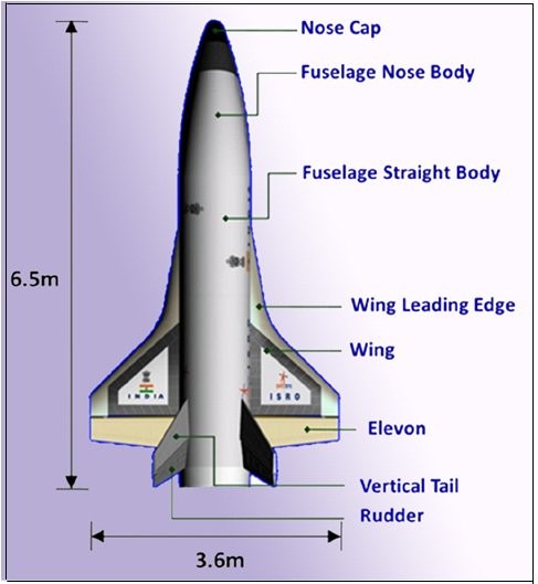
For the mission, the TDV was a scaled-down double-delta wing body space plane with canted twin vertical tails. The wing span is 3.6m and the length is 6.5m. The blunt canted ogive nosecone of the forebody provides better longitudinal stability. The wing consists of a double-delta plan-form with leading edge sweep back. Elevons that have both the function of elevators and ailerons provide the pitch and roll control. The TDV’s twin swept canted vertical tails with double-wedge air-foil section provide good directional stability and controllability at high angles of attack. Rudders on the vertical tails provide direction control and pitch-trim during supersonic speeds.
Booster
The solid rocket booster stage that launched the TDV also has four large movable base shroud fins in cruciform shape for ascent phase control and longitudinal stability.
Mission
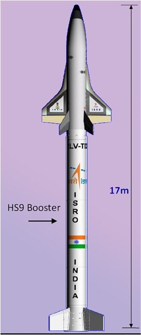
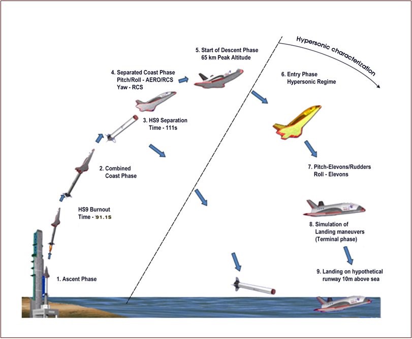
The TDV weighing 1750 Kgs was propelled as part of the ascent by a slow burning 11-meter long solid rocket booster that burnt out around 90 seconds at an altitude of 33Kms. The booster and TDV continued in a combined coast up to 44Kms altitude when the dynamic pressure has reduced enough for a safe separation. The TDV continued on an unpowered coast after separation of the booster up to an altitude of 65 Kms with a peak Mach number of around 5 before starting its descent. The descent of the space plane from that altitude had a reentry around Mach 4 that ended with a splash down in the sea, 412 Kms from the launch pad.
The mission had quite a few challenges – optimal sizing of the base shroud fins to ensure ascent phase control in all directions, robust ascent control system and Digital Auto Pilot (DAP) design to counter high aerodynamic moment instability coefficient, meeting required lift-to-drag ratio at hypersonic regime and high angles of attack during reentry, meeting required directional controls in descent phase using elevon rudder and Reaction Control System (RCS), robust descent DAP design to handle trim scheduling of wide range of Mach numbers and angles of attack, provide sufficient lift-to-drag ratio at low speeds to limit the sink rate before landing, minimise the aerodynamic heating to required levels for the given material, minimize the centre of pressure movement with Mach number, work within space constraints requiring a centralized Hydraulic Power generating Unit (HPU) controlling both stages one of which is an expendable stage, meet requirements of long hydraulic plumbing network, material processing challenges and other Quality Assurance (QA) challenges.
Do take a moment to subscribe to our email newsletter here. We will not sell your email address to a third party, and you can unsubscribe anytime.
The technology demonstration helped ISRO understand and evaluate the hypersonic aerothermodynamics of the double-delta winged body, hypersonic reentry, autonomous Navigation, Guidance and Control (NGC) schemes, design of airframe structure, integrated flight management, reusable Thermal Protection System (TPS), Flush Air Data System (FADS) and re-entry mission management. According to ISRO Chairman Dr. K. Sivan, “Comprehensive data generated in flight validated the design and development process and has provided enough confidence for ISRO to take the next leap in the arena of RLV. Necessary infrastructure and test facilities were augmented, extensive simulations were done prior to the flight; there were no anomalies in the entire flight regimes”.
Around 17 scaled down models were made and tested in the tunnels. The total number of wind tunnel tests conducted was around 4000. Around 968 flight measurements were taken during the RLV TD in different flight regimes.
<!––nextpage––>
Navigation Guidance and Control (NGC)
The NGC system of the RLV TD is a very mission critical system and it is also ISRO’s most complex NGC system ever developed for any of its launchers. The complex auto-pilot software in the NGC system helps the hypersonic vehicle assess its accurate position, velocity, acceleration and other parameters and guides the hypersonic vehicle autonomously towards its landing location by controlling the vehicle’s aerodynamic control surfaces (elevons, rudders, fins) and RCS. Unlike traditional expendable launch vehicles, NGC for reusable vehicles cover both ascent and descent.
Navigation
Inertial Navigation System (INS), GPS AIded Navigation System (GAINS) and Radar Altimeter (RA) were used for navigation to measure air state parameters like angle of attack, angle of side slip, bank angle, dynamic pressure, altitude and Mach number from coasting to Mach numbers greater than 2. For Mach numbers less than 2, Ceramic Servo Accelerometer Package (CSAP) was used for measuring vehicle acceleration in all three directions to achieve auto-pilot control.
Guidance
In the ascend powered phase, the guidance scheme uses altitude-based open loop quaternion steering. After booster separation when the TDV is still ascending to a peak altitude the guidance scheme is to orient its angle of attack from zero to a predefined value at a constant rate while keeping the side slip and bank angle zero. For the reentry phase up to Mach 2, an optimal Mach number versus angle of attack profile stored onboard is followed. In this phase below Mach 2, normal acceleration commands steer the vehicle based on stored tables. During the approach and landing phase, closed loop guidance commands the normal acceleration and bank angle to direct the TDV to the predetermined landing location. Trajectory design is generated onboard at the start of the approach and landing phase and tracked by a path controller. The guidance scheme allows re-target selection of landing location based on range to be covered and also has safe mode guidance to ensure vehicle safety. Iron bird test facility was used to test the integrated NGC system with around 130 simulations being carried out.
Ascent Phase Control
The Secondary Injection Thrust Vector Control (SITVC) system controls the vehicle pitch and yaw in the ascent phase. Reaction Control System (RCS) controls the vehicle roll from lift-off until dynamic pressure reaches 2 kPa. The booster stage also has four movable base shroud fins that provide ascent phase control and longitudinal stability. There are metallic fixed and composite movable parts in each fin used for pitch, yaw and roll controls which are used till booster separation.
Descent Phase Control
The space plane’s elevon, rudder and RCS provide the descent phase control. Symmetric deflection of elevons provide pitch control, asymmetric deflection provides roll control and rudder deflections provide yaw control during descent of the space plane. 8 RCS thrusters for pitch and yaw are placed in the top and bottom surface and side panels respectively of the aft fuselage. 4 RCS thrusters for roll are in the wing surface top and bottom. In the hypersonic regime of the descent where a high angle of attack is needed, the RCS provides the pitch, yaw and roll control. In the lower regimes, elevons are used for pitch and roll control. RCS and rudder are used for yaw control depending on whether the angle of attack is greater than 10 degrees or less than 10 degrees respectively.
The configuration of winged body plane on top of a rocket stage has aerodynamic moment instability coefficient that is 20 times more than that of a conventional multi-stage launch vehicle during the ascent phase. This issue was resolved by fast control system, powerful actuators with good bandwidth and faster sampling rates. Instead of the time-based gains scheduling adopted in normal launch vehicles, velocity-based gains scheduling was used to counter dynamic pressure variations.
Electrohydraulic Control Actuation System
There are 8 aerodynamic control surfaces on the RLV-TD – 2 elevons, 2 rudders on the TDV and 4 movable base shroud fins on the booster stage. The 8 control surfaces in two stages are controlled by an electrohydraulic actuation system, with a centralised Hydraulic Power generating Unit (HPU) located in the TDV due to space constraints in the base shroud. One of the challenges was to ensure the functioning of the system after the booster stage is expended after burnout. A unique hydraulic line disconnect and sealing device is used to disconnect and seal the TDV hydraulic circuit from the first stage booster hydraulic circuit at the end of the booster burnout.
Flush Air Data System (FADS)
FADS which is a mission-critical sub-system for hypersonic reentry vehicles, uses surface pressure measurements from the nose cap of the vehicle using a matrix of pressure orifices in and around the nose cone to derive air data parameters such as angle of attack, angle of side slip, Mach number etc. 9 pressure ports with 27 pressure sensors are used in the nose cap. Although in this RLV TD, FADS is used only in passive mode, it could be used in the active loop in subsequent flights. FADS is used below Mach 2 and corresponding altitudes less than 20kms, where the accuracy of navigation-based estimate of air state parameters from systems like Inertial Navigation Systems (INS) is reduced due to the role of winds speeds and errors in derivations. Above this altitude and especially above altitudes of 35-40 Kms FADS is ineffective and the vehicle relies on air data parameters derived from INS adjusted with latest wind data and atmospheric properties.
Materials and Thermal Protection System (TPS)
The technology demonstrator helped in the selection and use of materials like special alloys, composites and insulation materials for developing an RLV TD. It is critical that the right materials and Thermal Protection System (TPS) be chosen for the components that are bound to experience high thermal and pressure loads. Nose cap which would experience very high temperatures is made of carbon-carbon composite. The leeward region of the TDV has highly curved surfaces with a lower heat load. So, aluminum alloy and TPS made of Flexible External Insulation (FEI) with ceramic coating has been used. Windward region uses aluminum alloy and TPS made of waterproofed silica tiles. Vertical tail leading edges have to bear very high thermal and pressure loads and so are made of Inconel alloy. Rudder is made of low carbon steel alloy. Wing leading edge is made of low carbon steel alloy. The Elevon component required a material of high specific strength and good mechanical properties at elevated temperatures and hence titanium alloy has been used.
Next steps
The Landing Experiment (LEX) which tests the autonomous landing capability of the RLV TD on a runway will be the next tests to be carried out, which ISRO is planning sometime in 2019. As part of the test, the RLV TD will be lifted by a helicopter and dropped from 3.5kms altitude to test the controlled descent using navigation guidance and control and to land on a run way and bring it to a halt. After this test, the next step will the orbital reentry of the vehicle – the Return Flight Experiment (REX).
According to ISRO, “In future, this vehicle will be scaled up to become the first stage of India’s reusable two stage orbital launch vehicle”. In the actual Reusable Launch Vehicle, the vehicle will be the first stage and the second stage will be a rocket stage carrying the payloads. The actual vehicle is likely to be powered by the SCE-200 semi cryogenic engine. A scramjet engine could be integrated into the fuselage of the vehicle in the future. It will be interesting to follow the future developments of this reusable vehicle.


Semi Cryo Rockets ( First and Second stage ) will be re-usable ? Space X Style recovery to a barge ??
Any info on Payload / Earth Orbit.
First Launch with a Satellite in Nov 2021 ???
The vehicle (space plane) which will be the first stage containing the semi-cryogenic engine, will be reusable since it can land back.
ISRO have not stated their plans yet for the second stage, whether they will recover it or not. Potentially they can either recover the second stage by reentry and land in the ocean using parachute and float or recovery it using a vertical land in SpaceX style.
ISRO has not stated any payload numbers yet. My estimate is payload to LEO can be anywhere from 500kg small satellites to big satellites up to 4 or 5 tons. The size of payload will depend on engine used, whether scramjet engine is additionally used and how big the actual vehicle will be (The tech demo is only a scaled down version of the actual).
ISRO has stated that they will get the semi-Cryo engine ready by 2021 and then a clustered semi-cryo by 2024. So this will probably be around 2026.
I want to know about second stage landing ….space x style or not?
As of October 30, 2022, I can find no mention of anything happening with RLV-TD since the May of 2016 test-launch. What has happened with it in the last 6+ years, operationally speaking?
A reply to would be appreciated. A link to a *recent* web-posting would be fine.
Thank-you.